The installation shown here is being done on a 139QMB 50cc GY6 scooter
engine. I was using a 72cc big bore kit. Installation of larger or
smaller (even stock replacement) kits should be very similar. Even
125-150cc GY6 procedures should be nearly identical. Some specifications
(torque specs, ring end gap, etc..)may vary for different applications.
I
like to start by pulling the engine out of the scooter and putting it
up on my workbench. In many cases the engine can be worked on while
installed in the scooter, but the frame design of some scooters prevents
big bore kit installation while the engine is still in the scooter. If
you have any doubt about your ability to access the engine or properly
identify timing marks you should consider removing the engine. Pulling
the engine generally involves removing the carburetor, rear shock(s),
starter connections, grounds, brake cable/hose, and the engine mount
bolt. You can find more info about engine removal HERE.
Remove
the carburetor if it was not removing during the process of taking the
engine out of the scooter. You can see the carburetor removal process in
this VIDEO.
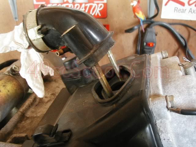
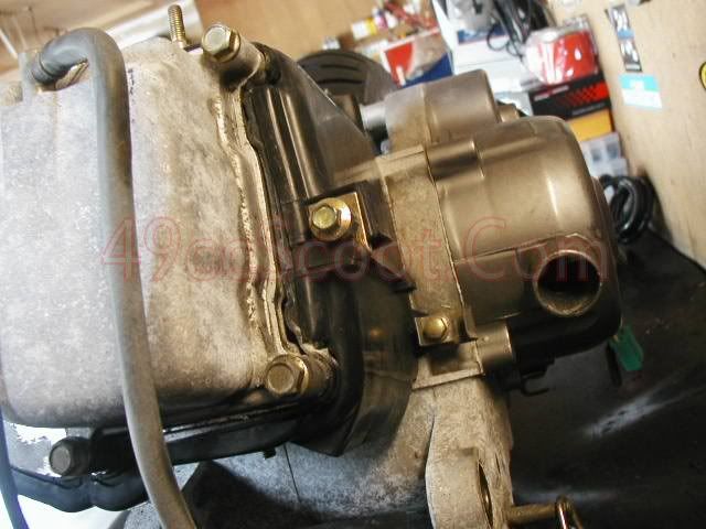
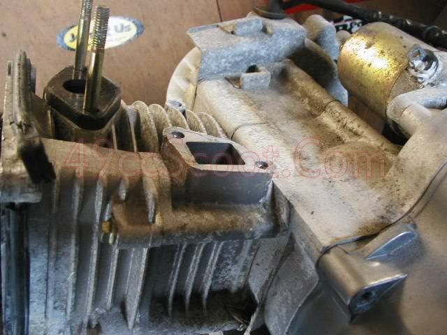
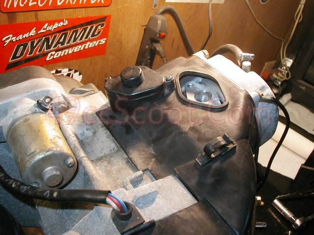
The next step is to remove the two nuts holding the intake manifold. Then slide the manifold off of the studs.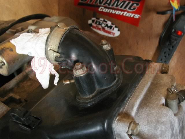
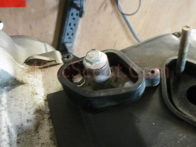
Now
remove the two screws holding the cam chain tensioner cover in place
and remove the cover. This step is not always necessary, but sometimes
it's easier to maneuver the engine covers with this off.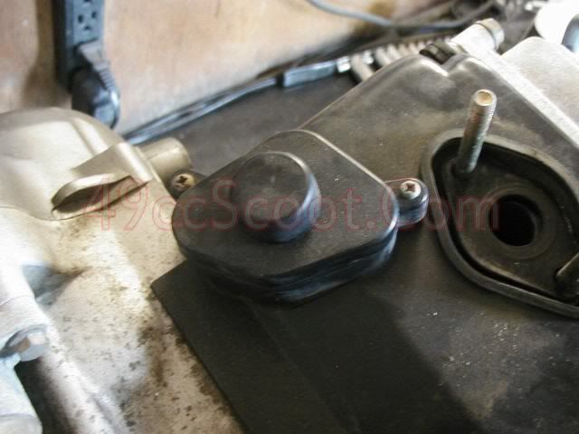
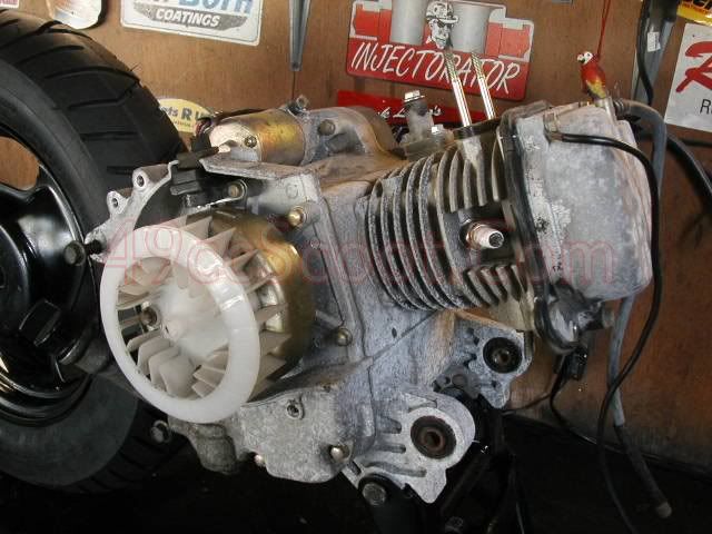
Next, remove the bolts holding the engine and fan shrouds on and remove the shrouds.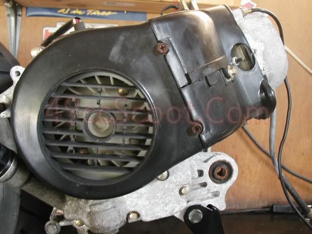
Remove
the 4 bolts holding the valve cover on and remove the valve cover. Some
models may only have 2 bolts. You may have a ground wire with a ring
terminal under one bolt. 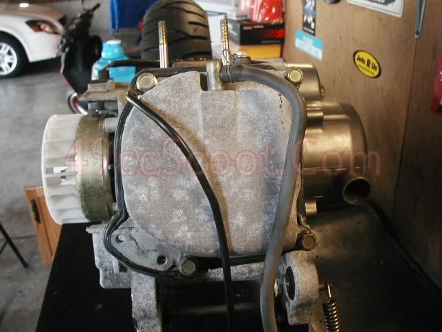
Rotate the flywheel until the "T" mark on the flywheel lines up with the cast in timing mark on the engine case.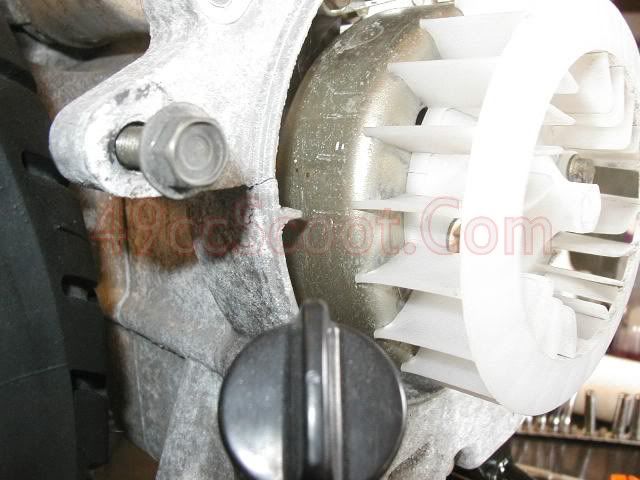
The
cam sprocket should look like the image below. The large hole should be
to the very front of the engine, perpendicular to the top edge of the
cylinder head. The two smaller holes should be parallel to the top edge
of the cylinder head. If the marks appear to be on the wrong side of the
sprocket, rotate the flywheel 360 degrees to line the timing marks up
again, which should move the cam sprocket 180 degrees and line the marks
up properly. 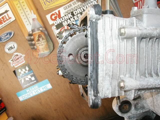
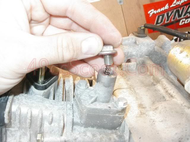
Now
remove the bolt, gasket, and spring in the cam chain tensioner. Some
models may have a screw with a knob that looks like a flathead screw
below it. For those models, just remove the screw.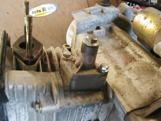
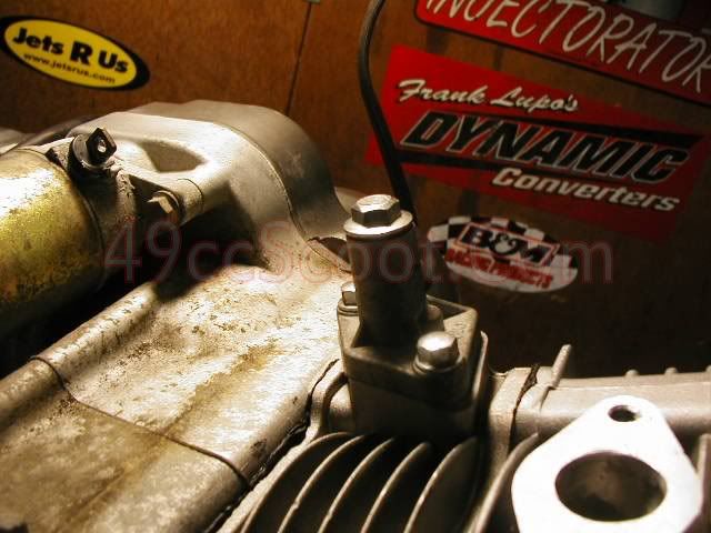
Next, remove the two bolts holding it and remove the cam chain tensioner.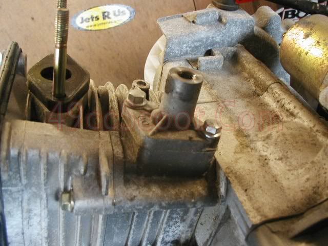
Remove the four nuts holding the camshaft holder and rocker assembly in place and remove the cam holder.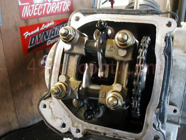
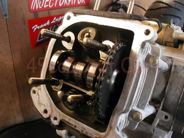
Remove the camshaft from the cam chain and pull the cam out of the cylinder head.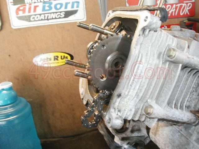
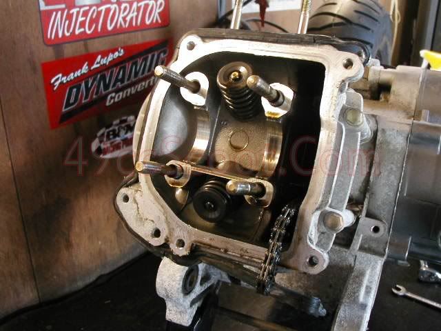
Now remove the two bolts securing the cylinder and head to the engine case.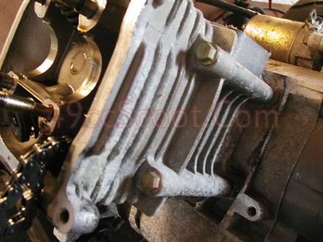
Pull the head off of the cylinder and studs.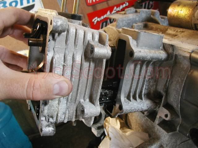
Next, remove the head gasket.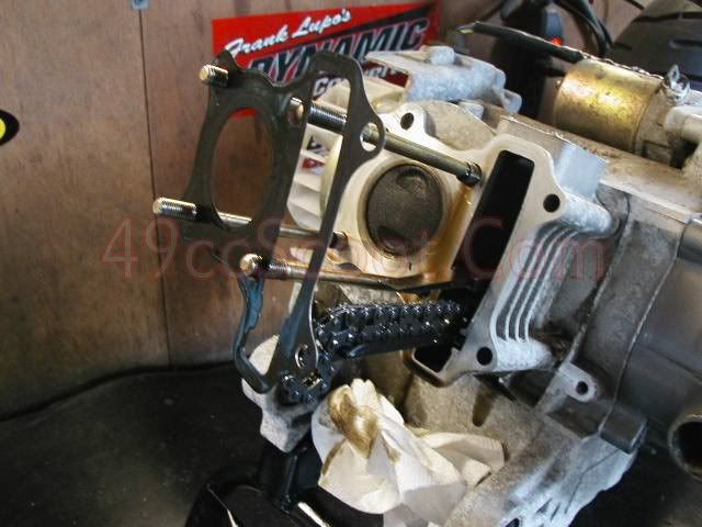
This
would be a good time to check the position of your piston in the bore.
Some Chinese scooter engines have been found with the flywheel
improperly machined or marked in a way that the T on the flywheel does
not correspond with true TDC (Top Dead Center). TDC is when the piston
is at it's highest point in the bore. If the flywheel is off
significantly, you may notice that the piston will go higher in the bore
than when the flywheel is set to the T mark. If this happens you should
replace the flywheel. Improper valve timing caused by an improperly
machined or marked flywheel and subsequently installing the cam in the
wrong position can lead to severe engine damage and/or poor performance.
This step is not generally listed in BBK how-tos and it is not
something that I think the majority of BBK installers will find, but
taking just a moment to look now may save you a lot of time or money in
the near future if something happens to be very far off.
Now
you'll need to free the cylinder from the engine case. Sometimes it will
just pull off, but not usually. You may need to tap it gently with a
rubber mallet while pulling on it to break it free. If that wont work,
you can try to gently pry the cylinder loose. Be careful not to damage
the case or cylinder mating surfaces and do not pry directly against any
mating surfaces.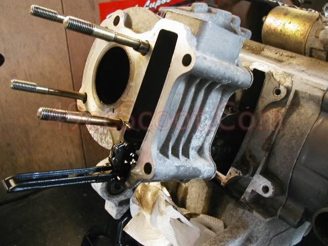
Remove the lower camshaft chain guide by simply pulling it outward.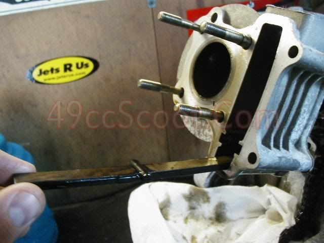
Pull the cylinder the rest of the way off.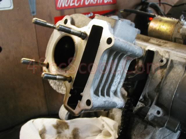
Now
remove the guides left in the cylinder or cylinder head. They should
pull out by hand or with pliers. Be sure not to crush them if using
pliers. If you deform them, try to reshape them or replace them.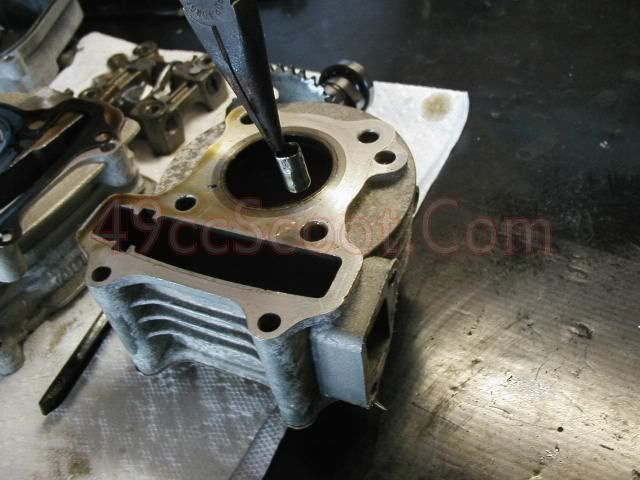
The
next step is to remove the circlips from the piston. Circlips are the
little clips that hold the wristpin in place inside of the piston. They
can be pulled out using needle nose pliers. You may want to stuff some
rags into the crankcase before attempting to remove the clips, just in
case one gets away from you. You don't want metal bits lost inside of
the engine cases.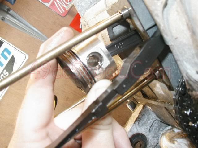
Once
the circlips are removed, you can push the wristpin out and take the
piston off of the connecting rod. There are special tools to pull the
wristpin, but you can use a very small socket to push the pin out if ti
won't move easily. Be careful not to apply force to the connecting rod.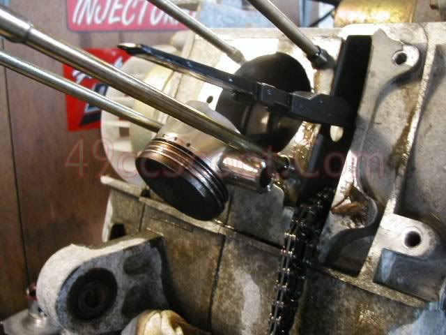
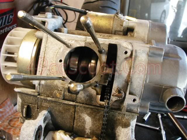
It's
a good idea to stuff some rags into the bore and camshaft chain
openings in the case to keep debris out while you do some prep work if
you didn't do it earlier when removing the piston.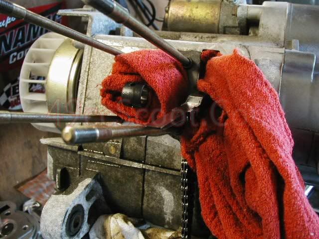
Now
it's time to begin prepping your big bore kit for installation. Of
course you need to start by setting the big bore kit beside the stock
cylinder and piston so you can imagine the additional power you'll be
feeling with the new larger parts. While you are comparing, make sure
the bolt patterns are the same and look for any other potential issues.
The image below shows the difference between a stock 49cc 139QMB 39mm
cylinder and piston and a 72cc 47mm big bore kit for the 139QMB GY6.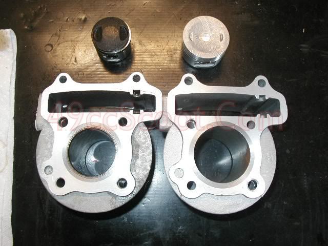
Next,
you will want to prep your piston rings. Start by determining where
your piston rings should be installed on the piston. You should have a
total of five piston rings. Two thick metal rings, two very thin rings,
and one wavy piston ring. The two thick rings are called compression
rings, the other three are often referred to as one oil control ring
because they all fit into one ring land. The thin rings (rails) on the
outside edges, sandwiching the wavy ring (expander) in the center. As
their names imply, the top two rings are primarily used to control
compression and seal the cylinder and the lower rings are used to
control oiling.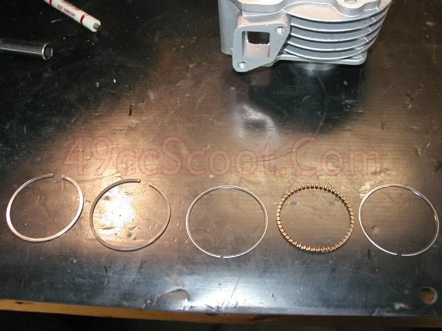
Take
a close look at the compression rings. They are usually meant to be
installed in a certain order. Sometimes they are colored to let you know
which is the top ring and middle ring and sometimes they will be
labeled with a "1" and a "2" or other markings. A common coloring is one
black and one silver compression ring. In this case, the silver ring
should be the top ring and the black ring is the second/middle ring.
While
you are checking out the compression rings, take note of any markings.
Only one side of the ring should have markings on it. This is the side
of the ring that will face up when installed on the piston.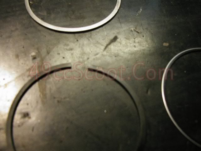
Now
that you know where all of the rings go, it's time to set the ring end
gap on the compression rings. Ring end gap is the distance between the
ends of a piston ring when it is installed in the cylinder. An end gap
that is too small can cause cylinder scuffing or ring failure and too
large of a gap will cause poor sealing and excessive blowby.
You'll
need to determine the distance to set the end gap. A good rule of thumb
is to set the end gap for the top compression ring to .004" per inch of
cylinder bore. Set the second end gap to .005" per inch of cylinder
bore. Many ignore the oil rails, those thin rings for oil control, but
you may wish to check and set it to 0.004" per inch of bore. Don't mess
with the expander ring. If your cylinder kit included it's own
specifications, use those.
Top Compression Ring End Gap = Bore Diameter" x .004"
Second Compression Ring End Gap = Bore Diameter" x .005"
Since these measurements are done in inches, you'll need to convert your bore diameter from mm to in.
Bore Diameter In Millimeters / 25.4 = Bore Diameter In Inches
For example, my 72cc big bore kit uses a 47mm bore.
47mm / 25.4 = 1.85"
1.85" x .004" = .007"
1.85" x .005" = .009"
I'll need to set my top compression ring's end gap to .007" and the second compression ring's end gap to .009".
To
set end gap, begin by placing the piston ring in the cylinder. Make
sure the marks are facing up just as it would be installed on the
piston.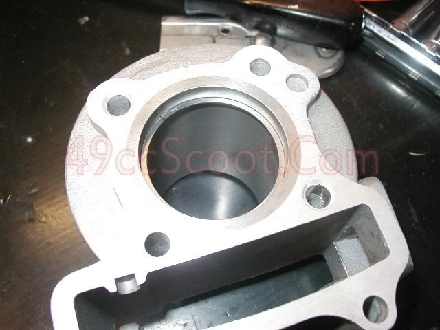
Use the piston to make sure the ring is installed straight so you can get an accurate measurement.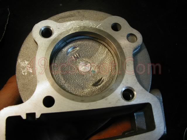
Now use feeler gauges to measure the distance between the ring's ends.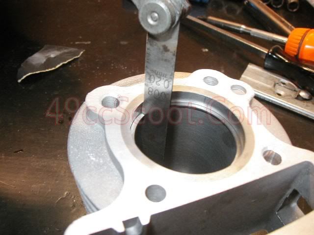
If
the distance is too small you can file the ends of the ring and
recheck. Be careful not to damage the ring. Apply light pressure and try
to maintain the original angle of the ring's ends. Most only file one
ring end. Always file from the outside of the ring to the inside. Check
the end gap frequently. You don't want to file them down farther than
specs and material goes pretty quickly. Remove any rough edges/burrs if
present when you finish, but do not bevel the edges or remove any
material that you don't have to. If the end gap is too large your only
option is to get new rings or if they are close to the gap needed, just
use them.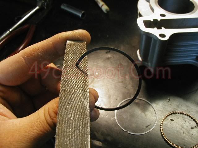
Once
your rings are gapped properly, it's time to install them on the
piston. I suggest using a piston ring expander tool. You can pick one up
pretty cheap from most auto parts stores or possibly rent one long
enough to do the job. You can install rings by hand, being careful not
to bend or expand the rings too far or you will risk breaking them.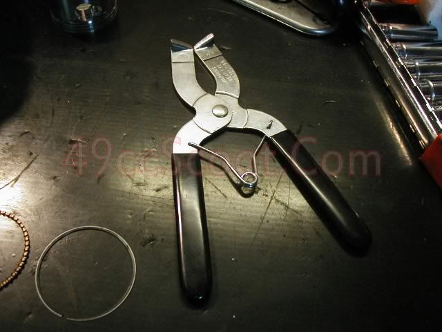
Start
by putting the top compression ring in the expander tool and opening it
just wide enough to fit over the piston. Be very careful not to spread
the ring too far and break it. 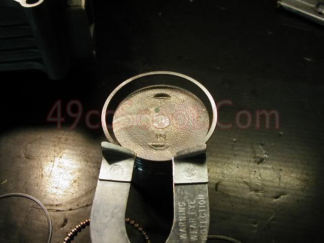
Move
the ring into position in the top ring land and slowly release the
pressure from the piston ring expander. Make sure the ring is in the
ring land all the way around the piston. Some people like to use
assembly lube or oil to coat the piston and/or rings for this process.
I do it dry.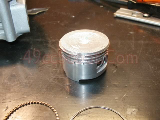
Repeat
this procedure, placing the 2nd compression ring into the middle ring
land. When installing the oil control rings, make sure the two thin
rings are on each side of the wavy ring. It is often easiest to install
the wavy ring first, then the thin rings on the edges. The expander ring
should be installed with it's ends butted and the ends facing down
toward the bottom of the piston.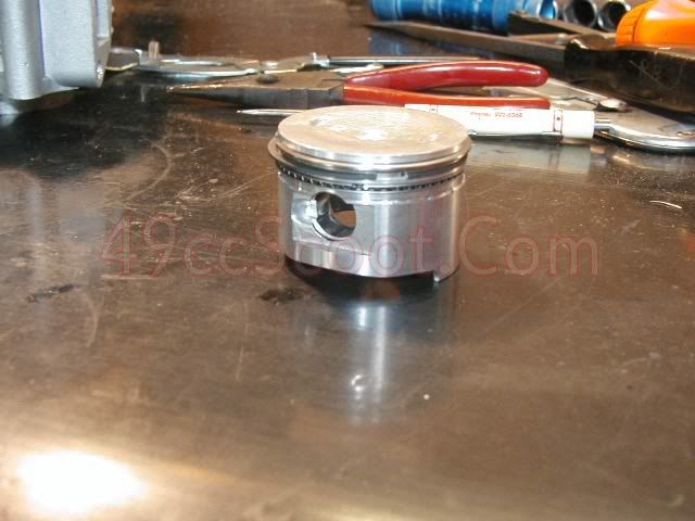
Apply
assembly lube or oil to the wrist pin, the guide in the piston, and the
inside of the connecting rod and slide the wrist pin in as far as you
can without it protruding into the center of the piston.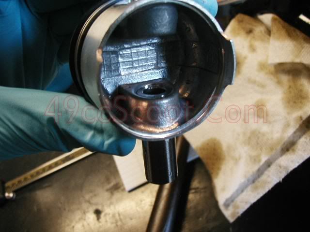
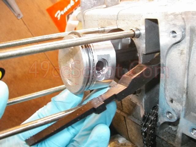
I
remove or reposition the rags guarding the crankcase from debris to
give me a little more room for movement in this step. Note the position
of the valve reliefs in the top of the piston. The one labeled "IN"
should be at the top when installed. This indicates the intake side or
intake valve. Slide the wrist pin through the connecting rod so that
both ends are flush with the inside cutout of the piston.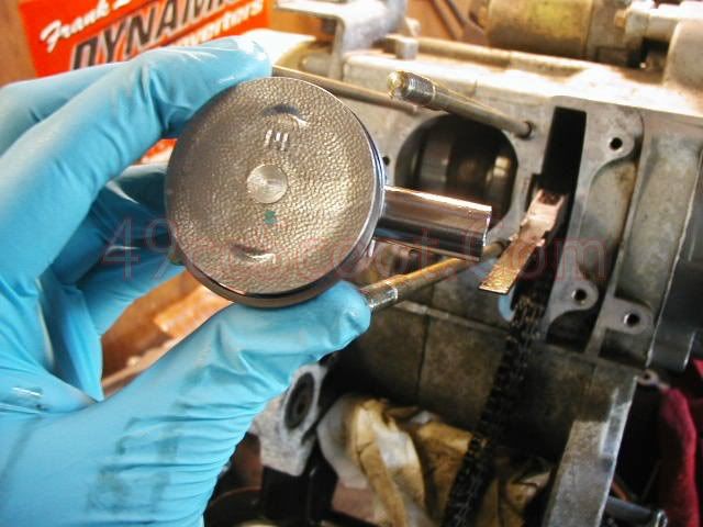
I
replace the rags in the crankcase for the next step. Circlips sometimes
spring out when you are trying to install them and you don't want them
in your crankcase.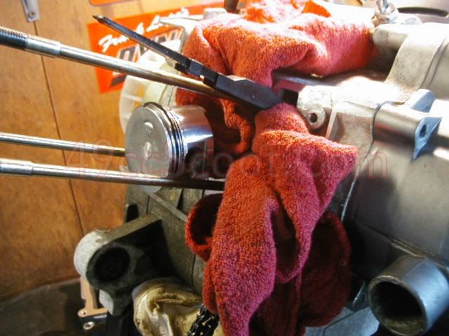
Install
the circlips on both sides of the wrist pin. This can be tricky until
you get the hang of it. I push one side into the receiver groove for the
circlip. Then grab the other side with a pair of needle nose pliers.
Twist and push a little and the circlip should go into place. You may
find that another method works better for you.
Make sure the
circlip is tight in it's groove. Move the clip so that the opening is
toward the top or bottom, not sides, of the piston.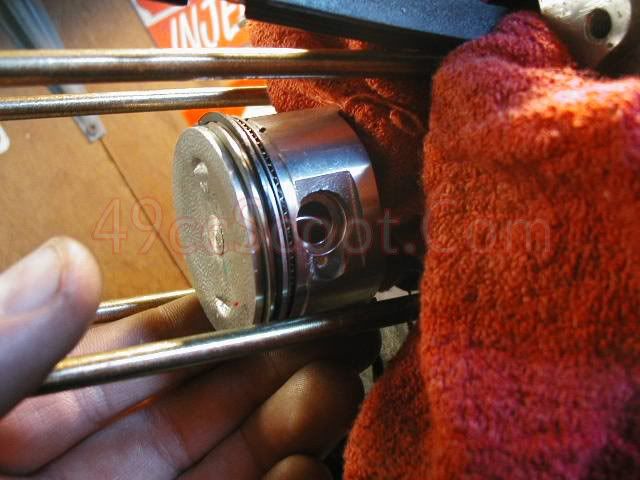
Clean the mating surface of the block and install the base gasket and locator dowels.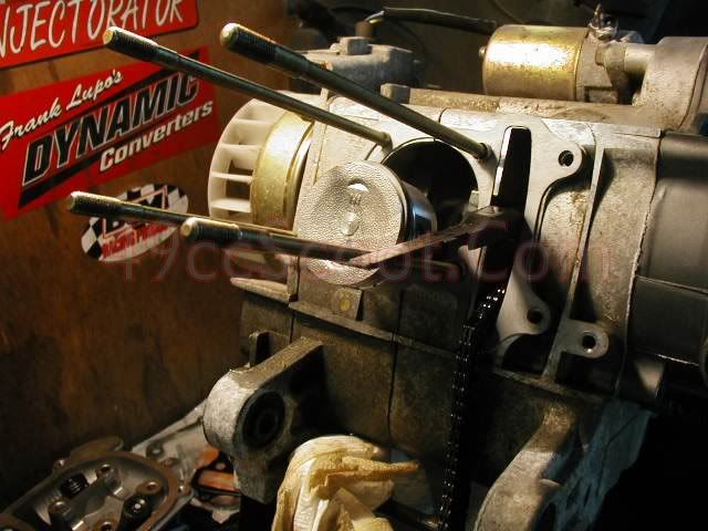
Put
a coat of assembly lube or oil on the piston and on the inside of the
cylinder and rotate the piston rings so that no end gaps are lining up
with each other. See the image below from a service manual for more
detail.
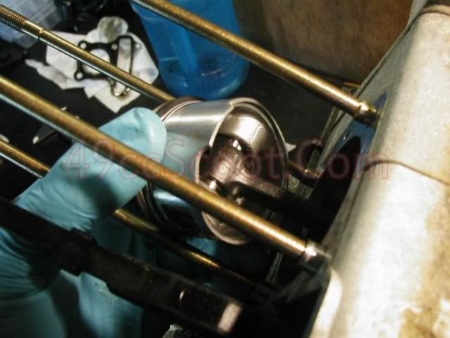
Gently
slide the cylinder over the piston, being sure you don't snag any
rings. You will probably need to use your fingers to keep the rings
compressed as you slide the cylinder over them. Take your time and don't
force anything. If the piston won't go, recheck all or your rings and
retry.
Once the rings are all inside of the cylinder, pull the
camshaft tensioner though the cylinder. You can see in this pic that I
forgot to replace the dowels and had to remove the cylinder to put them
in place. D'oh.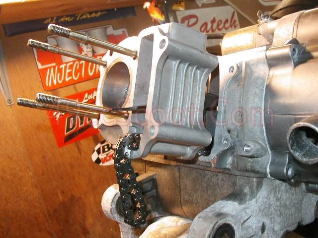
Slide the cylinder in place until it is up against the base gasket and engine case.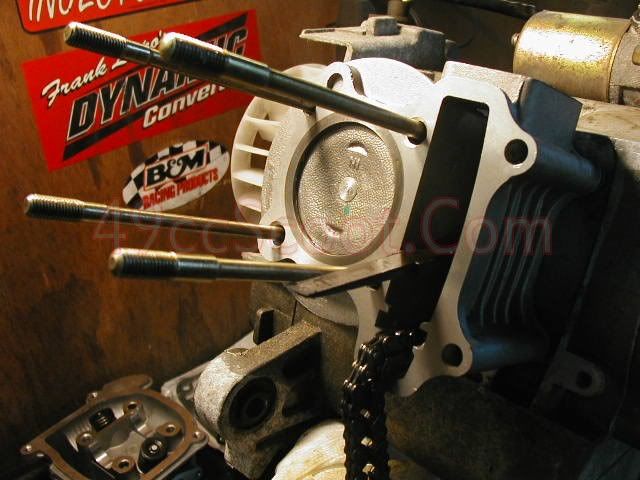
Next, slide the camshaft chain guide into place in the cylinder.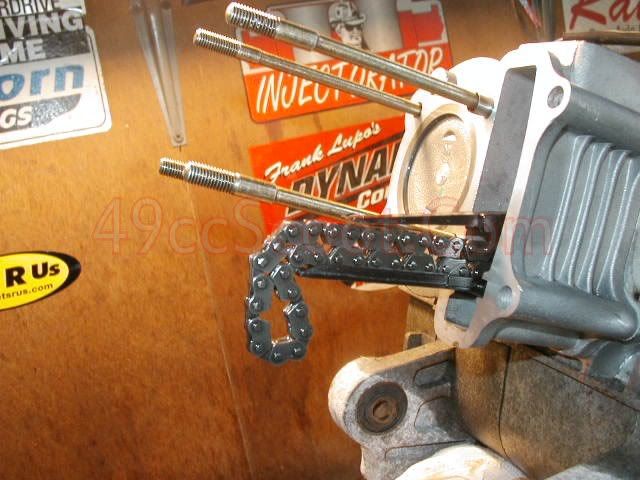
Install the locator dowels and the head gasket.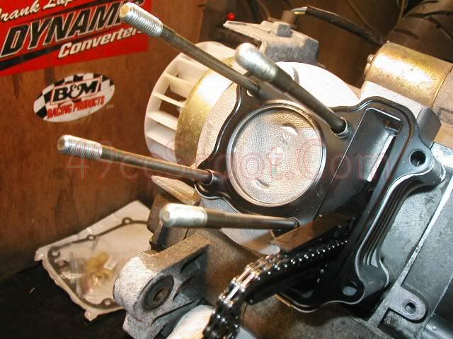
Slide the cylinder head into place with the intake port facing up.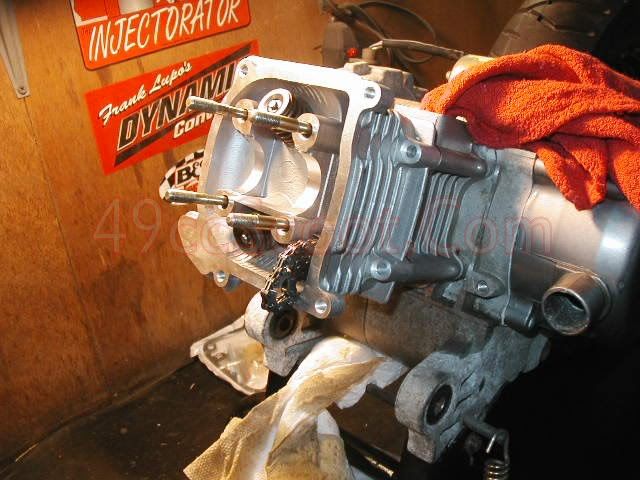
Install the two bolts on the side of the cylinder finger tight.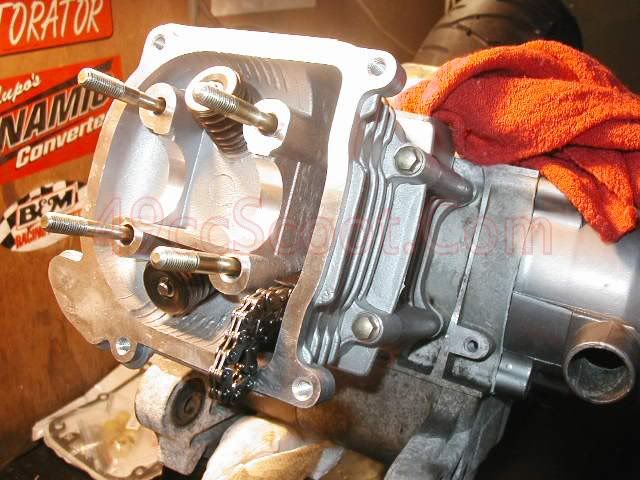
Check to ensure the engine is still on top dead center ("T").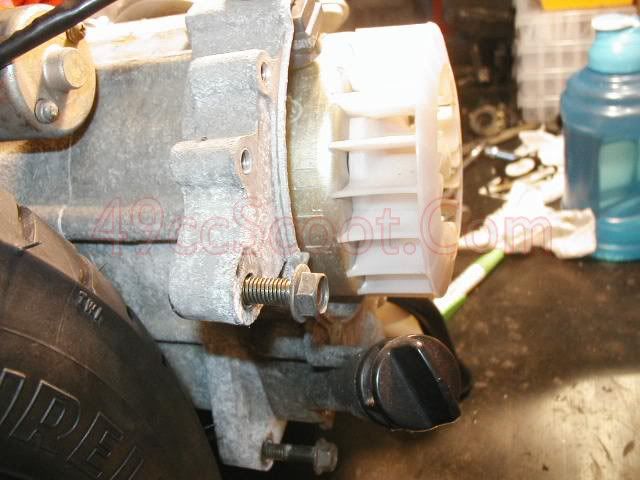
Apply
assembly lube or oil to the bearings and lobes of the camshaft and the
races in the cylinder head and camshaft holder/rocker assembly.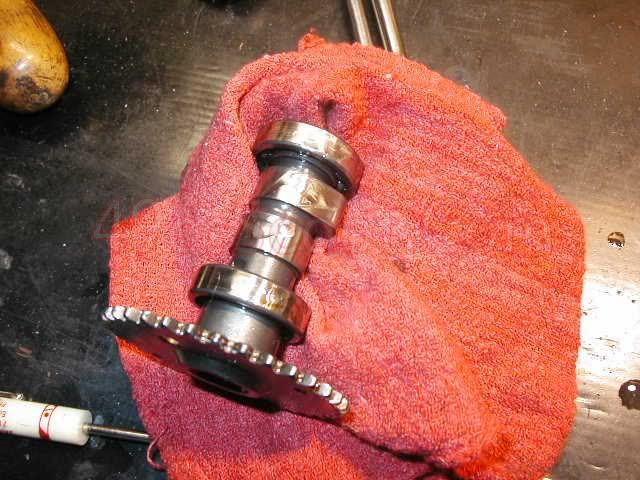
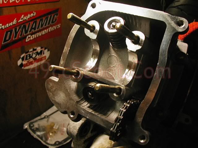
Install
the camshaft into the head and cam chain. If installed properly the
timing marks on the cam sprocket should line up just like before. If
they are off a little, remove and retry until you get the marks aligned
as shown while the flywheel is set to the T mark.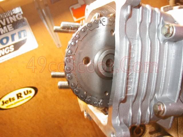
Put the locator dowels in place and slide the camshaft holder/rocker assembly into place over the cam.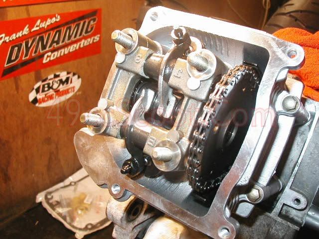
Install
the four copper washers and nuts to secure the camshaft holder. Torque
them to 13 ft-lbs (156 in-lbs) in a criss-cross pattern. Torque the
cylinder/head bolts on the side of the engine to 8 ft-lbs (96 in-lbs).
It is best to torque fasteners in steps. For example, torque the head
bolts to 5, 10, and finally 13ft-lbs rather than jumping straight to
final torque. Some install the cylinder without a torque wrench, but a
properly calibrated torque wrench insures even and appropriate torque
with no guesswork.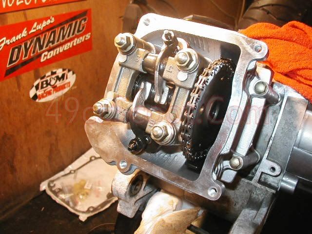
Next,
reset the cam chain tensioner. If yours is like the one pictured,
simply hold the locking mechanism in and push the pin in as far as it
goes. If your tensioner is the screw top model, turn the flat head screw
while you push the pin in.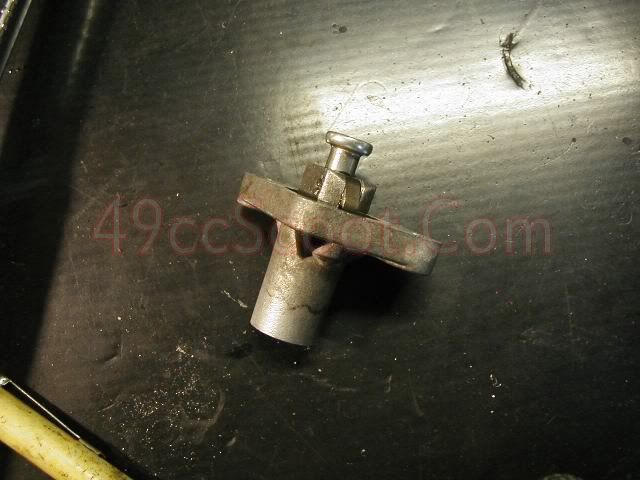
Install the cam chain tensioner onto the cylinder with a new gasket.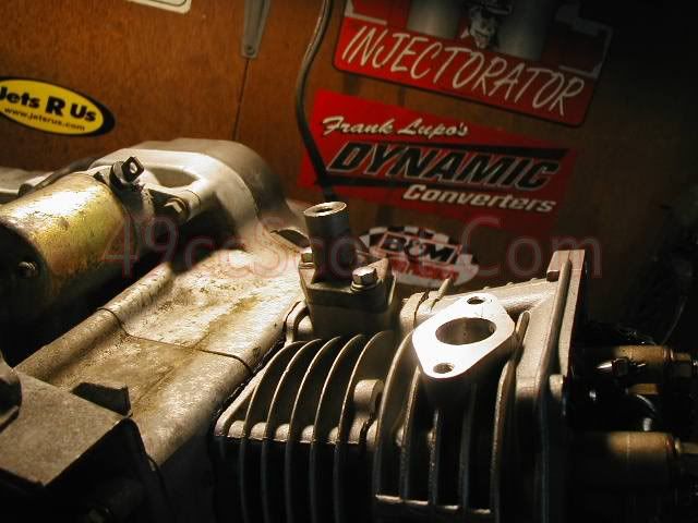
Insert the spring and install the bolt and gasket, or simply replace the screw on some models.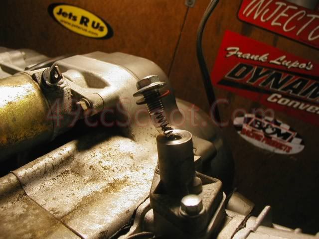
Use
feeler gauges to check the valve lash. Apply a thin coating of oil and
insert the feeler gauge between the tip of the valve and the rocker
arm's tip. The correct measurement should show only slight resistance
when moving the feeler gauge back and forth. I use 0.002"-0.003" of
clearance for the intake valve and 0.0025"-.004" of clearance for the
exhaust valve. This is not an exact science, but stay withing a range of
0.002-0.005" in most cases. Valve noise is normal and if there is no
valve noise when you get to start the engine, the valves are too tight.
If the valve noise is excessive, you may need to use a smaller setting
than you initially chose. CLICK HERE to see a video showing valve adjustment.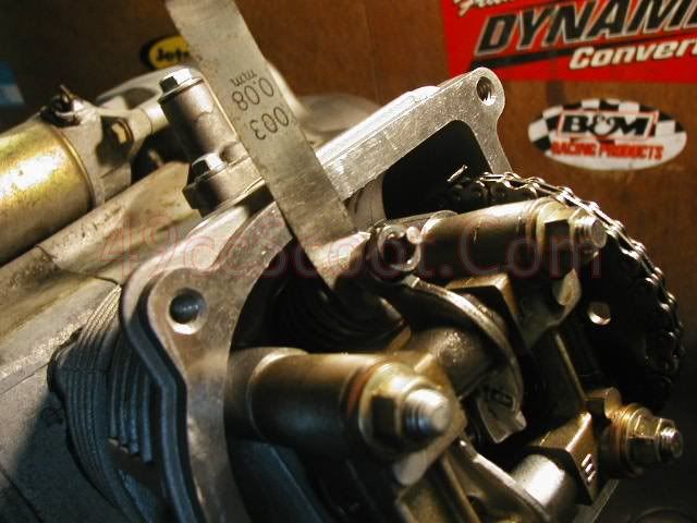
If
the valve clearance does not match up to your desired specifications,
loosen the nut securing the adjuster using a 9mm wrench. Now you should
be able to turn the adjuster with your fingers. Insert the appropriate
feeler gauge and move it back and forth while you turn the adjuster.
Stop when you feel slight resistance. Now hold the adjuster using a
small adjustable wrench or pliers while you tighten the nut with a
wrench. Once you have the nut tight, make sure you haven't changed the
valve clearance when tightening the nut. If you have altered valve lash,
repeat the process.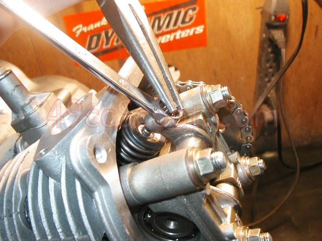
Inspect the valve cover gasket and replace if necessary. Most of the time this can be reused without issue.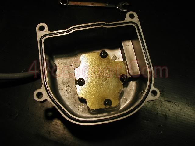
Install the valve cover and tighten the bolts in a criss-cross pattern. Don't forget the wire if there was one attached earlier.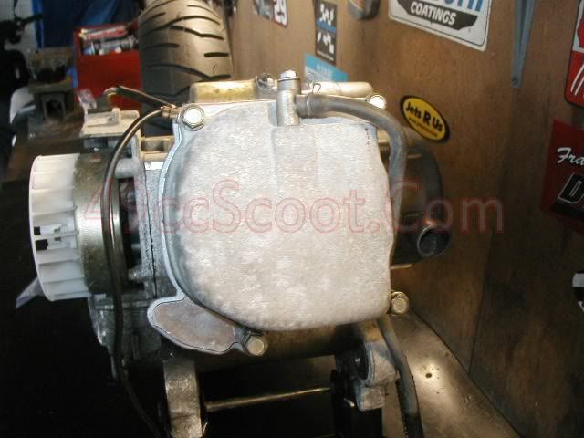
Now is a good time to inspect your valve cover breather hose for cracks or wear and replace it if necessary.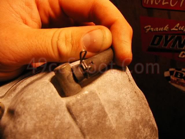
Get
a new spark plug and gap it to your desired specifications. I usually
gap them to .028". If you are using iridium plugs be very careful
checking and gapping them. The tip is fragile and can be easily broken. HERE is more spark plug gapping information.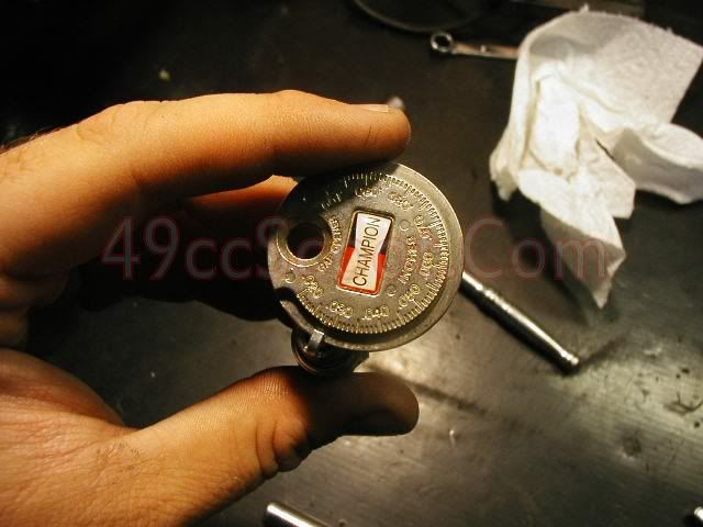
Once your spark plug is gapped properly, apply a dab of anti-sieze to the threads and install it in the cylinder head.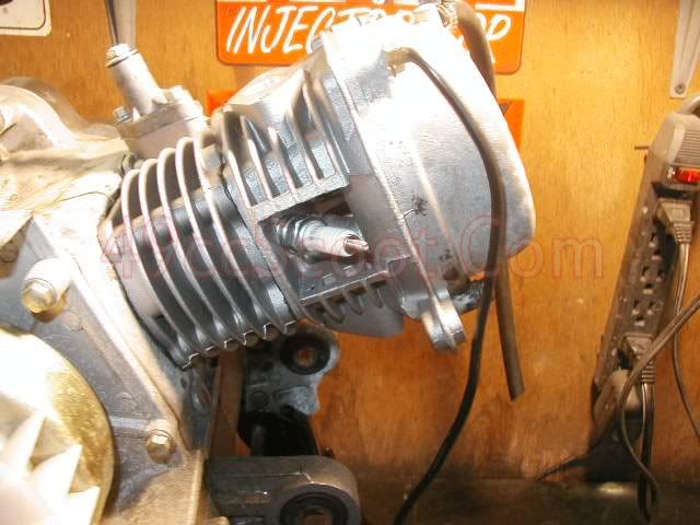
Re-install the engine covers and cam chain tensioner cover.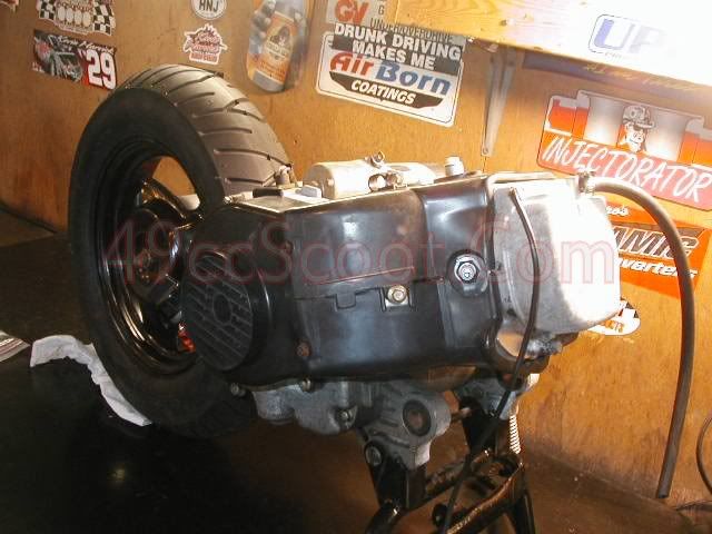
If
your are using a new cylinder head, you may need to install intake
manifold studs into it. Tighten them to finger tight. They will tighten
more when you install the intake manifold nuts.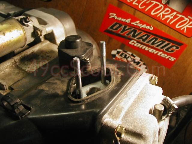
If
you haven't done it already, remove the intake spacer from the old
head. Check the condition of the o-rings and/or gaskets and replace them
if necessary. 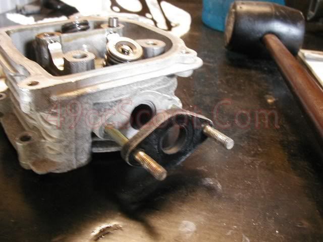
Install the spacer on the new cylinder head.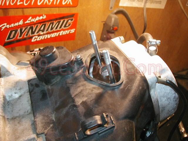
Slide the intake manifold over the studs.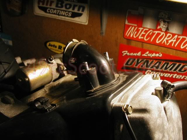
Install the intake manifold nuts and tighten them to 8 ft-lbs (96 in-lbs).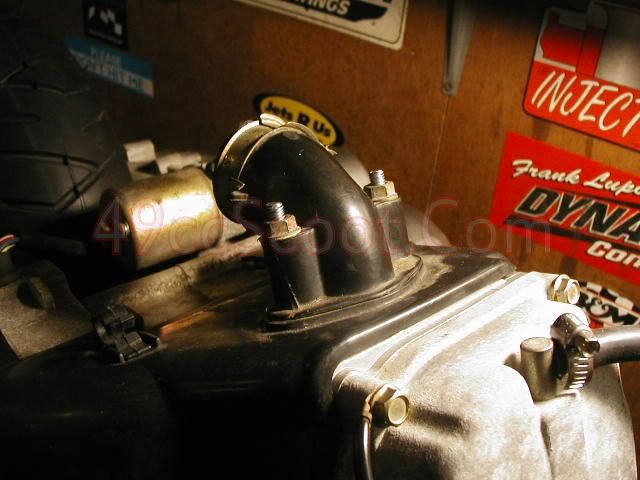
Install exhaust studs if using a new cylinder head.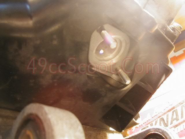
Now
you are ready to install your carburetor, air filter, and exhaust. Once
that's done you can put the engine back into your scooter.
I would suggest performing an engine oil change prior to starting the engine. CLICK HERE for more information about oil changes.
Once
you get your new engine running, adjust the idle mixture and speed
settings. There are multiple theories about engine break-in, and I don't
believe everyone will ever agree one exact procedure. For that reason,
I'll link you to THIS THREAD containing a multiple views on the process.
The
carburetor should be tuned and I'd also suggest going over the CVT
tune. There's a chance that you'll be alright with whatever jetting and
settings you currently have, but I strongly advise going through a
tuning process. Take your time tuning the carburetor. It will pay off in
both performance and reliability. You can find a simple trial and error
method for tuning for the carb and CVT in THIS VIDEO.